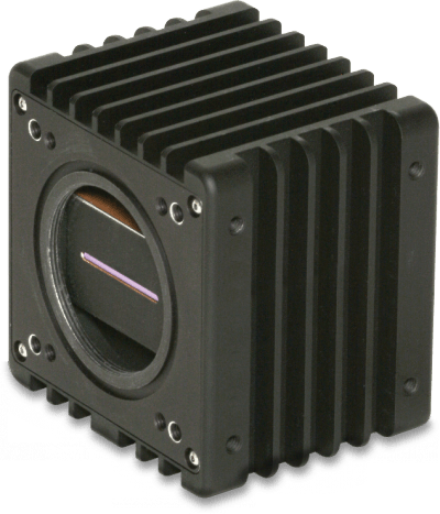
The SUI 1024-LDM camera is a high-speed 1024-pixel linescan InGaAs camera for use in high-resolution imaging through silicon wafers, blocks or ingots.
Details
Features
Specifications
Applications
The 1024-LDM camera is a high-speed 1024-pixel linescan InGaAs camera designed for precise imaging. It detects issues such as misalignment, occlusions, inclusions or cracks early in the manufacturing process of Integrated circuits or solar cells, reducing costly rework. Additionally, it excels in high-speed imaging of free-falling molten glass gobs and inspecting agricultural raw materials or pharmaceutical mixes.
With flexible line rates up to 45,956 lines per second (lps) and a compact depth, the mechanical design gives system integrators the flexibility to fit the camera inside their inspection machines. A photoetch mask sharply defines the array’s 25-µm aperture, ensuring high time and spatial resolution. The alternate 500-µm pixel height trades time resolution for increased sensitivity in photoluminescence imaging.
- High quantum efficiency and dynamic range
- Integrate-while-read snapshot acquisition
- Predefined line rates from 80 to 45,956 lps user programmable
- Wavelength response over 0.8 µm to 1.7 µm
- 1024 x 25-µm pixel pitch with the aperture heights of 25 or 500 µm
- 14-bit base Camera Link® compatible
- Operating temperature range of -10 to +50°C
- Light-tight mount for spectrometers
- Mounts easily to optics benches or MV systems with tripod, front or side fastener hole patterns
- Optional adapters for F-mount or C-mount, lenses (C-mount lenses may not fully illuminate the full width of the 25.6 mm wide arrays)
- Mechanical
-
Dimensions
6.1 cm x 7.37 cm x 7.62 cm
2.4 in x 2.9 in x 3.00 in
Length excludes I/O connectors, and lens adapter -
Weight
< 450 g or 1 lbs (no lens or adapter)
-
Lens Mount
M42x1-6H with 5.7 mm to image plane
one, fixed distance C-Mount adapter or
adjustable distance F-Mount adapter (see ordering info) -
Spectrometer Mount
4 tapped 8-32 holes in 2 inch square pattern
4 tapped M4x0.7-6H holes spaced 5 cm x 4 cm (h x w)
O-Ring light seal, 1.9 inch diameter, 1/16th thickness -
Camera Tripod Mount
2 tapped ¼-20 holes alternating on ¾” (19 .05 mm) spacing with 2 tapped M6-6H holes
-
Side Wall Mounts
4 tapped M4x0.7-6H holes, 5 x 4.5 cm spacing (h x d)
- Environmental & Power
-
Operating Case Temperature
-10°C to +50°C
-
Storage Temperature
- 20°C to 70°C
-
Humidity
Non-condensing
-
Power Requirements
AC Adapter: 100-240 VAC, 47-63 Hz, < 1.0 A
DC Voltage: 7-16 V, < 6 W at 25°C, <9 W at 50°C
In-rush Current: < 1.5 A peak - Interfaces
-
Control
SDR 26-pin connector ( Base Camera Link®)
-
Image Data
SDR 26-pin connector ( Base Camera Link®)
-
Power
Hirose HR10-7R-6PA receptacle
Mates with HR10-7P-6S or SN4-8-6(P) -
Sync Output
SMA: 5 V, 50 W series terminated,
active high: integration active -
Trigger: Input
SMA, Low < 0.5, 3 V > high < 5 V
-
Status LED
Green: TEC locked at setpoint
Red: TEC unlocked
Blinking: Timing or triggering error - Regulatory Compliance
-
CE
Meets class A level for emission, immunity & ESD standards
-
FCC
Meets requirements for Part 15, Subpart B, Class A, 2006
- Electro-Optical Performance
-
Sensor Format 1
1024 pixels on 25 μm pitch with 4 readout ADCs
-
Optical Aperture (pixel height) 1
500 μm or 25 μm (square pixel sharply defined by mask on detector surface)
-
Peak Quantum Efficiency 1
> 70%
-
Gain Capacitor Setting
0.1 pF 1.0 pF 10.0 pF Typical Specification Typical Specification Typical Specification Net full well capacity (Me-) 2 1.6 >1.1 15.9 >9.2 150 >110 Gain (e-/cnt) 1,3 107 1000 9600 Temporal noise (rms counts) 1,2 8 <12 3.5 <4.5 2.5 <3.5 Dynamic range 1,2,4 1900:1 >1350:1 2600:1 >2100:1 3100:1 >2600:1 Differential non-linearity 1,2 +/- 0.8% < +/- 1.2% +/- 0.8% < +/- 1.2% +/- 0.8% < +/- 1.5% -
Bad Pixel Specification
White, dark, noisy or pixels exceeding +/- 10 of the mean value when illuminated at 50% of full well. Number of bad pixels limited to a maximum of 1% of array total; no bad neighbors within 5 pixels
-
Exposure Time 1,3
0.018 ms to 12.8 ms in 20 preset steps or to > 1 s with user programmed or via the width of the ext. trigger
-
Trigger Modes 3
Free run, single line per trigger, external variable exposure, or gated burst
-
Sync Output
SMA coaxial connector: digital output signal, high during integration
-
External Trigger 3
Via frame grabber CC1 signal or SMA coaxial connector on rear panel with selectable polarity
-
External Variable ET
User set by the duration of trigger signal (minimum ET pulse: 10 μs)
-
External Trigger Jitter
+/-1 clock cycle: nominally 80 ns with internal ET
-
Pixel Rate
50 Mpix/s max with 14-bit words transferred on each Camera Link strobe clock cycle
-
Digital Output Format
14-bit base Camera Link®; recommend NI PCIe-1427 or equivalent frame grabber
-
Readout Mode
Integrate while read, differential double sampling
-
Corrections (preset OPRs)
Factory calibrated gain, offset, and bad pixel replace, applicable to the center 90% of the array
-
Resolution
1024 x 1
-
Pixel Pitch
25 μm
-
Line Rate
45,956 lps
-
Spectral Response
0.8 to 1.7 μm
-
1 Actual formats and performance governed by user-selected SUI linear array purchased with camera (dark current may limit longest usable ET)
2 Camera readout noise limited for low & medium gain settings; dark shot noise limited for high gain settings
3User selectable by command over Camera Link® serial lines
4Dynamic range limited to maximum values shown when camera operated at exposure times shorter than 28 μs due to reduced full well capacity - Ordering Information
-
Camera Model1 Part number Max. Line rate1 Pitch Pixels FPA length Aperture (height) SU1024-LDM-1.7RT-0025/LC 8000-0555 >46,956 lps 25 μm 1024 25.6 mm 25 μm SU1024-LDM-1.7RT-0500/LC 8000-0661 >46,956 lps 25 μm 1024 25.6 mm 500 μm -
1Cameras include the photodiode array, whose characteristics dominate camera performance; see the array datasheet for more information
2Accessory Kits: Include power supply, carrying case, SMA-BNC trigger in and sync out cables, o-ring, carrying case, mini-CD with manual and free SUI Image Analysis software for National Instruments Camera Link frame grabbers.
3Part Numbers: Kit with F-mount adapter: 8000-0528. Kit with C-mount: 8000-0530. Kit without lens adapter: 8000-0529
- Inspection through polished silicon wafers or blocks
- Machine vision for ultra-high speed inspection, materials classification, sorting and/or monitoring of continuous processes, for example for food or agricultural product sorting
- Fast absorption or emission spectroscopy for combustion research, moisture, lipids, proteins or other molecular vibration bands in the 0.8 µm-1.7 µm range
Important export information
These commodities, technology and/or software are subject to the Export Administration Act as promulgated by the Export Administration Regulations. Diversion contrary to U.S. law is prohibited.
| 1024-LDM Linescan Camera | |
| Export Classification: | EAR EAR99 |
| 1024-LDM Linescan Camera - Square Pixel | |
| Export Classification: | EAR6A003.b.4.a |
RTX does not assume any liability that should arise from the provision of this information in connection with national customs laws and regulations or other international trade requirements.